


1. Product Introduction
The remote control for automatic cutting of track car rope saw is suitable for track type rope saw cutting machines. It uses the 485 Modbus RTU protocol to control the left and right track frequency converters, as well as the large motor frequency conversion speed control start and the front, rear, left and right direction controllers. And it can read the working current of the large motor frequency converter through the 485 Modbus RTU protocol. By analyzing and comparing the current of the large motor, the speed of the left and right tracks can be automatically adjusted in real time to achieve automatic cutting function.
2. Product functional features
1. Adopting 433MHz wireless communication technology, with a wireless operating distance of 100 meters.
2. Adopt automatic frequency hopping function and use 32 sets of wireless remote controllers simultaneously, without affecting each other.
3. Supports all frequency converters with 485 Modbus RTU protocol, and currently compatible frequency converter brands include:Shanghai Xielin, Fuji, Huichuan, Zhongchen, INVT, and . For brands that are not compatible, please contact us for customization.
4. Support speed regulation, starting, and current reading of large motor frequency converters.
5. Support left and right track frequency converter speed regulation, starting, front, back, left and right control.
6. Support linear correction of left and right track frequency converters to keep the machine walking in a straight line.
7. Support automatic cutting function of rope saw, automatically adjust the left and right track speed in real time according to the current information of the large motor. 8. It is also compatible with direct IO output control for motor start and stop, and analog voltage output control for motor speed.
3. Product specifications
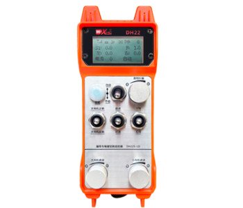
-英文-2.jpg)
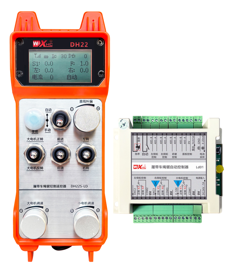
4. Product Function Introduction
-英文-3-1(1).jpg)
Notes: ①Screen display:
-英文-3.jpg)
②Mode switch:
Using a 2-level switch, it is possible to switch between automatic and manual modes, and the corresponding mode will be displayed on the screen for switching.
③Enable:
Combination buttons, some operations require holding down the enable button for operation, see the instructions for each switch for details.
④Large motor switch:
Using a 3-speed reset switch, pulling this switch can control the forward and reverse ro t ation of the large motor. After releasing it, the state will remain, and there will be corresponding displays on the screen. The S1↑ arrow indicates forward rotation, and the S1 ↓ arrow indicates everse rotation.
⑤Small motor forward/reverse switch:
The small motor is equipped with a 3-speed self-locking switch in front of it. Pressing the enable button and pulling this switch can control the small motor to move forward and backward, and the corresponding display will appear on the screen.The ↑↑ arrow represents forward, and the ↓↓ arrow represents backward.
⑥ Straight line correction:
Using a multi turn encoder knob, press the enable button, turn the knob right, and display the straight line correction: Df: The left turn knob increases by 1 unit per rotation, and the left motor speed increases by 0.1 unit; Turn left knob, straight line correction display: Df: On the right, every turn of the knob increases by 1 unit, and the speed of the right motor increases by 0.1 unit.
⑦Small motor turning switch:
Using a 3-speed reset switch, when manually operated, the small motor can be controlled to turn left or right. Once released, the remote control will automatically stop this action. In the forward state, when this switch is turned, the corresponding display will appear on the screen. The ←↑ arrow indicates left turn, and the ↑→ arrow indicates right turn. When in reverse mode, turn this switch and the corresponding display will appear on the screen. The ←↓ arrow indicates left turn, and the ↓→ arrow indicates right turn.
⑧ Large motor speed regulation:
Using a multi turn encoder knob, rotating 1 grid each time, the speed value of the large motor changes by approximately 0.2 units. Fast rotation can quickly modify the speed value of the large motor.
⑨ Small motor speed regulation:
Using a multi turn encoder knob, in manual mode, press the enable button and then rotate one grid at a time,the speed value of the left and right small motors changes by about 0.1 units, and quick rotation can quickly modify the speed value of the small motor. In automatic mode, press the enable button and rotate one grid at a time,the speed limit value F of the small motor changes by approximately 0.1 units. Rapid rotation can quickly modify the speed limit value of the small motor.
⑩ Remote control power switch :
The remote control display screen is turned on.
5. Product accessory diagram
-英文-5.jpg)
6. Product Installation Guide
6.1 Product installation steps
1. Install the receiver into the electrical cabinet through the buckle on the back, or install it into the cabinet through the screw holes at the four corners of the receiver.
2. Refer to our receiver wiring diagram and compare it with your on-site equipment. Connect the equipment to the receiver through wires.
3. After fixing the receiver, it is necessary to connect the antenna equipped with the receiver and install or place the outer end of the antenna outside the electrical cabinet. It is recommended to place it on the top of the electrical cabinet for the best signal effect. It is forbidden to leave the antenna unconnected or place it inside the electrical cabinet, as it may cause the signal to be unusable.
4. Finally, install the battery on the remote control, tighten the battery cover, and turn on the power switch of the remote control. After the remote control display screen shows the normal working interface, remote control operations can be performed.
6.2 Receiver installation dimensions
-英文-7.jpg)
6.3 Receiver Wiring Reference Diagram
-英文-7-2.jpg)
7. Product operation instructions
-英文-8.jpg)
7.2 Parameter setting of frequency converter
1. Command source selection: Communication command channel
2. Main frequency source selection: communication given
3. Baud rate: 19200
4. Data format: No verification, data format<8-N-1>
5. Local address: Set the left frequency converter to 1, the right frequency converter to 2, and the large motor frequency converter to 3
7.3 Remote Control Operation Instructions
1. Power on the machine, turn on the remote control, enter the remote control backend, set the remote control backend parameters, mainly setting the small motor and large motor frequency converter models: (skip this step if the machine manufacturer has already set it);
2. Set the parameters of the frequency converter (skip this step if the machine manufacturer has already set it);
3. Set the remote control to manual mode, and then use the remote control to move the machine to the working position;
4. In manual mode, set the cutting current of the large motor to IC and the speed of the large motor
5. Switch to automatic mode and set the cutting speed limit F value for the small motor;
6. In automatic mode, turn the large motor switch to forward to start the large motor, then turn the small motor switch to forward or reverse, and the remote control enters automatic cutting mode to start cutting.
8.Product troubleshooting
-英文-10.jpg)
9.Maintenance
1. Please use it in a dry environment at room temperature and pressure to extend its service life.
2. Please avoid using in abnormal environments such as rain and water bubbles to extend the service life.
3. Please keep the battery compartment and metal shrapnel area clean.
4. Please avoid damaging the remote control due to squeezing and falling.
5. If not used for a long time, please remove the battery and store the remote control and battery in a clean and safe place.
6.During storage and transportation, attention should be paid to moisture and shock resistance.
10. Safety Information
1. Please read the instructions carefully before use and prohibit non professionals from operating.
2. Please replace the battery in a timely manner when the battery is too low to avoid errors caused by insufficient power, which may result in the remote control being unable to operate.